


STMicroelectronics VNF1248F High-Side Switch Controller
STMicroelectronics VNF1248F High-Side Switch Controller offers a power MOSFET in a high-side configuration. The STMicro VNF1248F is developed for implementing an intelligent high-side switch in 12V, 24V, and 48V automotive applications. The control IC is interfaced to a host microcontroller via a 3.3V and 5V CMOS-compatible SPI interface and supplies protection and diagnostics for the system.
Features
- AEC-Q100 qualified
- General
- High-side switch control IC with e-fuse protection for automotive 12V, 24V, and 48V applications
- 32-bit ST-SPI interface compatible with 3.3V and 5V CMOS level
- 2-stage charge pump
- Gate drive for an external MOSFET in high-side configuration
- High precision uni-directional current sense through an external high side shunt resistor
- Input for an NTC resistor to monitor the external MOSFET temperature
- Very low standby current
- Device configuration lockout by a dedicated digital input pin
- Integrated ADC for TJ, VNTC, VOUT, VSENSE conversion
- Fast ADC for VDS, VSENSE conversion
- CCM: capacitive charging mode
- A few times programmable non-volatile memory (FTP NVM) embedded for the customer sector program/erase/read
- Direct input pin for hardware control of the external MOSFET gate pin
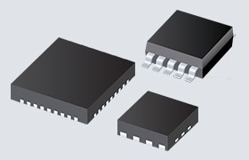
- Package QFN32L 5x5 package with wettable flanks
- Protections
- Battery undervoltage shutdown
- External MOSFET desaturation shutdown configurable via SPI
- Hard short circuit latch-off configurable via SPI
- Current vs time latch-off configurable via SPI (fuse-emulation)
- Device overtemperature shutdown
- External MOSFET overtemperature shutdown
- Reverse battery
- Loss of GND
Applications
- Specially intended for Automotive power distribution applications
- Intelligent high-current fuse replacement for automotive applications
Specifications
- 70V maximum transient supply voltage
- 6V to 60V operating voltage range
- 6V to 70V operating voltage range (extended)
- 75µA standby current (max.)
- 3V to 5.5V SPI I/O supply voltage
- 5µA SPI standby current (max.)
Board

STMicroelectronics EV-VNF1248F Evaluation Board
Integrates a high-side switch controller with intelligent fuse protection into prototype circuitry.
Block Diagram

COMPLETE YOUR DESIGN

STMicroelectronics Standard Products
A broad range of drop-in replacements for general-purpose analog ICs, discretes, and serial EEPROMs.
Published: 2025-09-30
| Updated: 2025-10-09